The CNC machining diagram serves as a visual guide that helps operators clearly understand the sequence of steps from preparation to finishing the part. This ensures tighter quality control and minimizes production risks. Let’s explore the CNC machining process in detail with 3Dmanufacturer!

Nội dung
What is CNC machining?
CNC (Computer Numerical Control) machining is a manufacturing technique that uses an automatic numerical control system to operate machinery according to pre-programmed instructions. This method allows for cutting material from a solid workpiece to create precise mechanical components based on digital technical drawings (CAD).
Depending on the motion between the tool and the workpiece, CNC machining is categorized into several techniques:
- CNC milling: The cutting tool rotates around the spindle and moves flexibly along the X, Y, and Z axes. Suitable for processing flat surfaces, grooves, holes, or parts with complex shapes.
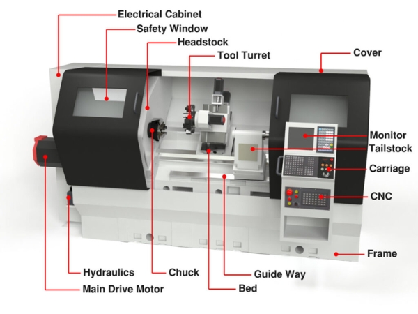
- CNC turning: The workpiece rotates around the spindle, while the cutting tool moves horizontally or vertically. This method is mainly used to create round parts such as shafts, tubes, threads, etc.
- CNC grinding: Uses a high-hardness grinding wheel to remove a thin layer of material on the surface to achieve precise dimensions and surface quality.
- Wire EDM (Electrical Discharge Machining): Uses an electrically conductive wire (usually copper or molybdenum) to cut material via electrical discharge. This non-contact process is ideal for hard materials and complex profiles that require high precision.
- CNC laser cutting/engraving: Uses a high-energy laser beam to melt, evaporate, or cut material at the focal point. Commonly used for engraving, cutting thin metal sheets, plastics, or wood with high precision.

Advantages of CNC machining
CNC machining represents a significant advancement over traditional mechanical processing methods. The application of numerical control systems provides numerous benefits, including:
- High accuracy: Computer-controlled operations reduce errors and meet strict dimensional and geometric requirements, especially for complex parts.
- Capability to process complex details: Effectively handles curved profiles, 3D surfaces, and intricate structures that traditional methods struggle with.
- Increased production efficiency: CNC machines can operate continuously with high automation, shortening machining cycles.
- Cost and time saving: Optimizes material usage, reduces product defects, and saves labor costs, leading to long-term savings despite high initial investment.
- Production flexibility: Easily switch programs to machine different parts or adjust designs quickly.
- Operational safety: Reduces direct contact with cutting tools, minimizing workplace accidents compared to manual machining.
- Consistency and uniformity: Produces parts with stable quality, ideal for mass production or high-precision technical applications.

CNC machining diagram
The CNC machining diagram illustrates the entire process from receiving the technical drawing to completing the product. It includes the following main steps: process analysis, toolpath design, control programming, simulation and verification, machine setup, and actual machining.
Analyzing the machining process
Before programming and operating a CNC machine, the first step is to thoroughly analyze the part to determine the most suitable manufacturing method. This stage involves:
- Interpreting technical drawings: Identifying the shape, dimensions, tolerances, surface finish, and material.
- Selecting appropriate CNC machine and fixture method for the part.
- Creating a logical machining process: Determining the sequence of operations, choosing tools, and Setup cutting parameters.
- Preparing a process sheet that outlines the steps, parameters, and technical requirements for each machining stage.
Toolpath design
Once the machining process is defined, the next step is to design an appropriate toolpath to ensure accurate and efficient machining. Specifically:
- Constructing the tool’s motion path across the part surface.
- Calculating transition points and height levels between tool movements to avoid collisions.
- Compensating tool radius, especially important when machining curved or angled profiles.
- Using CAM software to support complex profiles (2D, 2.5D, 3D…) and generate toolpaths.

NC programming
To enable the CNC machine to perform the intended tool movements, control programming – typically in the form of G-code – is required. This is a critical step in the CNC machining diagram, as it translates toolpath designs into specific commands that the machine can execute.
There are two common approaches to generating G-code:
- Manual programming: This method involves writing G-code line by line directly into the control system. It requires the programmer to have a strong understanding of CNC machine operations, coordinate systems, tool offsets, feed rates, spindle speeds, and machining logic.
- Automatic Programming (via CAD/CAM software): In this approach, computer-aided design (CAD) and computer-aided manufacturing (CAM) software are used to streamline the programming process. The software generates toolpaths based on the 3D model or 2D drawing and automatically converts them into G-code.
Program simulation and verification
Before actual machining begins, the control program must be thoroughly checked to prevent errors that could damage the part, tool, or machine. This verification step can be performed in two main ways:
- Manual inspection: Reviewing the G-code line by line and mentally visualizing the tool movements based on the programmed logic. This method is rarely used today due to its time-consuming nature and high reliance on the operator’s experience.
- Software simulation: Utilizing CAM software such as Mastercam, Fusion 360, or SolidCAM to simulate the machining process. These tools help visualize toolpaths, detect potential programming errors, and identify collisions or overcuts before the program is executed on the actual machine.
CNC machine setup (Setting)
To ensure accurate machining, operators must perform initial setup tasks to align the workpiece and tools. This includes:
- Positioning and clamping the workpiece on the machine table or fixture.
- Entering tool length, radius, and workpiece origin coordinates into the CNC control system.
- Verifying the dimensional chain closure, ensuring all elements from machine → tool → fixture → part are correctly defined so the machine can interpret positions and paths properly.
Example: On a CNC lathe, values like ZM, ZW, ZT, Z0… must be set to ensure precise cutting positions.
Actual machining
Once all the steps in the CNC machining diagram are completed, the machine is ready for operation. This stage involves:
- Uploading the G-code program to the machine controller.
- Reviewing the program on the control interface and performing a dry run (non-cutting simulation) to verify motion paths.
- Executing the actual machining process while closely monitoring operations to promptly identify and resolve any issues.
- Conducting a quality inspection of the finished part to ensure it meets all technical specifications.

Investing in an in-house CNC machining system to meet metalworking needs can incur significant upfront costs – especially when machining requirements are intermittent or not in high volume.
That’s why choosing metal CNC machining services at 3Dmanufacturer is a cost-effective solution, helping businesses optimize their budgets while eliminating unnecessary operating expenses during production.
3Dmanufacturer is the first fully online and automated CNC machining platform in Vietnam, offering a modern, streamlined experience for both individuals and businesses. Customers can easily place orders without the need to visit in person – simply access our website, upload your CAD drawings, customize technical specifications, and submit your machining request.
With just one click, 3Dmanufacturer’s automated quoting system instantly generates a machining cost estimate, allowing customers to save time and maintain full control over their production planning.
Mastering the CNC machining diagram ensures the process is technically sound, improving efficiency and production stability. Every step in the diagram plays a crucial role – from analyzing drawings, programming, simulation, to verification and execution. If you’re looking for a modern CNC machining solution, don’t hesitate to contact 3Dmanufacturer – your CNC order can be launched in just a few simple steps!